Hi,
I am creating this post to introduce the new project that I am joining. Let me put you in context first:
maybe you know already about Train modelling. Is a hobby for people who like trains and small things, modelling, dioramas, and other similar staff. You have a railroad layout and a set of trains, and you drive them over the layout and enjoy the view. Some people creates a mini-world around it looking for the most realistic scenarios.
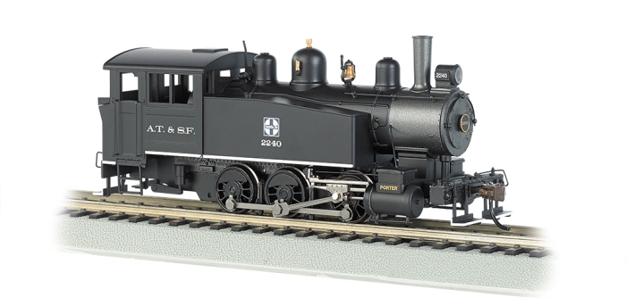
My dad owns a ver old set of H0 train set that works on an anagogic system. He created a layout for having them at home and drive them from time to time. The layout consists in two elipses sharing the center, one inside the other. There are two connections between them allowing trains to go from one to the other and get back. The full set runs on a 18DCV circuit ruled by two power supplies with a potentiometer to allow you regulate speed and direction. Every train consist in a Locomotive with a DC motor attached to the wheels for transferring the movement, and then behind all the wagons. Here’s a picture:
And here is an random layout taken from the internet: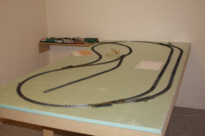
So, the railways act as conductors for the power and the wheels send the voltage to the Locomotive’s DC motors (some brands have a AC motor, but the railway is different and there are 3 lines for power conducting, something completely different). The amount of voltage sent to the Locomotive is decided in the controller.
At this point you probably noticed that this way, you can only drive one train at a time, or more than one, doing exactly the same as the others, as the signal will be the same for all of them. This project raises as the need of a solution for this situation, and the latest electronic components that I have found over the internet, and my knowledge with Arduino.
The aim for the project is to create a device as small as possible to be fit inside the locomotive (H0 is 1:87) and control it through digital signals. There are devices that will allow you to do it, and this is called DCC (digital command control) but the prices are very high, if you have a big set of trains that you would like to convert.
In the DCC approach, a constant power signal is sent through the railway and an encoded signal is mounted over it. This goes over the railroad constantly and every locomotive receives from the railroad the power to run, and the signal to be decoded. Once the locomotive read the signal, it checks if the signal is for this locomotive, and if this is the case, runs the command. This happens a lot of times per second, creating a sensation of continuos control.
My first idea was to create something similar, and send the signal over the railway. I have browsed the internet and found some related projects. Most of them refer only to the control side of the device. Actually all of them (the ones that I’ve seen and found) and they all use DCC ready locomotives. Is a valid approach but not suitable for my case.
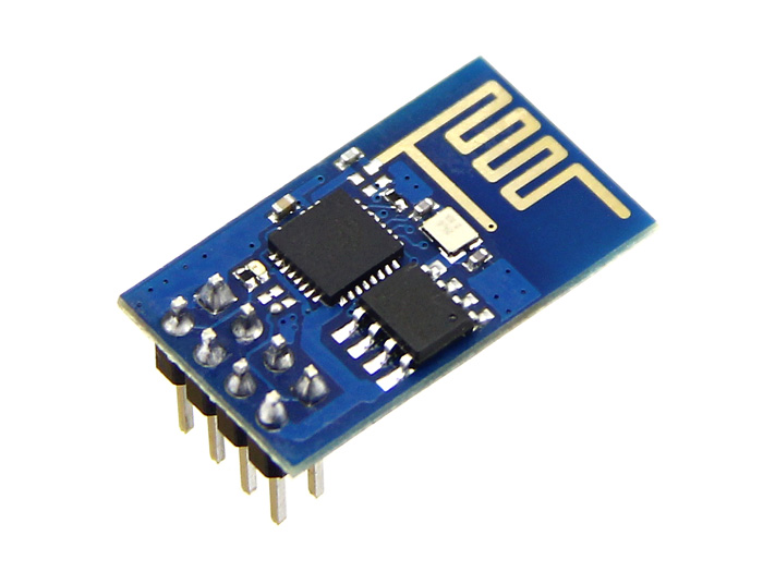
I thought about creating a decoder for the trains, but I have no information on how to do it, so if you, reader maybe know about something, please contact me. Instead, I’ve found this:
ESP8266 | Espressif 乐鑫
This is a micro controller with WiFi attached to it. My first idea was to control it with an arduino (ATMega) but it turned out that there is a full pic on it, and you can code it. There is no need to have the arduino. This is the perfect device for controlling mobile devices over IP.
The idea now is to send a constant power signal over the railway, and send the data over WiFi. For that, I just need to have a power supply to the device (it runs at 3.3V and trains around 18V), and control the motors with a DC motor driver. It looks promising.
Welcome to the project!
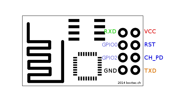
 In this model, you have an ADC (anagogic to digital converter) input, and several GPIO (General Purpose Input Output) pins. I have also bought two of them for the first prototypes.