Diecast Cars Privacy Policy

This policy applies to version 1.0.1 and lower versions of this Google Play application.

All data gathered by the application, including pictures, settings and data related to your car’s collection, is never uploaded to our servers (we don’t have any yet), never shared with any third party, and never used for any other purpose different than “Diecast Cars” application features.

None of your pictures is never leaving your devices unless you decide to perform such action, or in case any possible bug is hidden in the code. We want our user’s data to be secured and protected.

By installing the application you accept this policy.

In case you have any question, please do not hesitate in contacting us.

ESP8266 connection for programming

If you are about to start a project with Wifi functionality, this may be interesting for you:

As we have seen before, we will need two devices in this project:
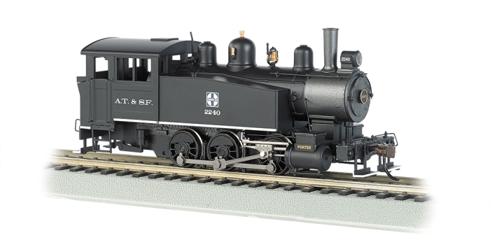
  • A Train receiver
  • A signal emitter

For the train receiver, the idea was to use an ATMega chip and control the DC motor using a L293D chip (H bridge) thanks to the PWM on the AtMega. The AtMega would receive the signal from the Wifi module that we are about to attach, the Esp8266.

I started reading about the Esp8266 and it turned out that the Esp8266 already has a pic in it, and it is possible to program it. This way, I do not need to deal with the ATMega communication with the Wifi Module, and the device can be even smaller.

I am going to talk about how you will need to setup your hardware to create a confortable environment for developing your software. For programming an Esp8266 module, you will need the following hardware (as a basis):

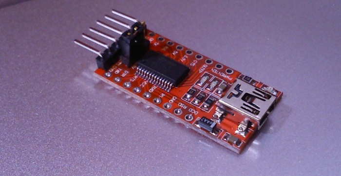
  • FTDI (Usb to serial) connector.
  • A breadboard or protoboard.
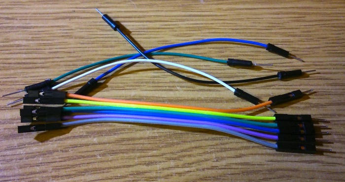
  • Some wires
  • Some 10K resistors

Optional but useful parts:

  • Two push switches

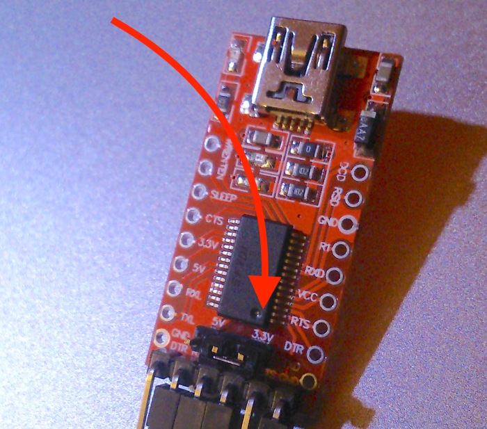
The FTDI will be required to send your data to your Esp8266. If you have an Arduino board, you can communicate with the Esp8266 by creating an extra Serial port, but in my tries, there where some random failures in the communication, so I would not use that way for sending a program to the Esp8266. The FTDI is a small device with a USB port at one side, and 6 pins for output at the other side. Usually they work at 5 V, but the Esp8266 requires 3.3V for power and levels. If you are about to buy one, please be sure to buy the one working at 3.3V. Here’s a pic of a FTDI:

DSC_0176

The breadboard will help you do the connections. You won’t need a very big one, just a standard will be enough:

71cbqkjtzvl-_sy355_

Wires are required to connect all components:

DSC_0172

10K resistors required to connect some Esp8266 pins:

DSC_0175

If you want to make your life easier, please get a pair of these push buttons:

DSC_0174

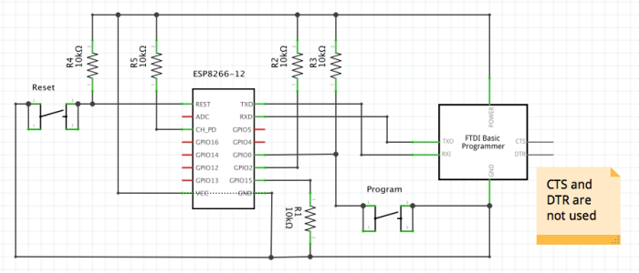
The scheme I used for programming the Esp8266 Rev 12 was the following:

scheme-full

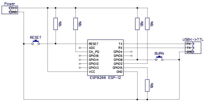
I have copied it from an image found on google images. The original circuit included a capacitor and another resistor at GPIO16, but I do not know why those are there:

scheme-full

I was using an external power supply, because I faced this issue when connecting to the FTDI:

  • The Serial port was available on the computer, but when connecting with the Jumper on 3.3V on FTDI, the port just brakes and I cannot select it anymore. I need to restart my computer.
  • If I use 5V I can burn the ESP8266.

However, these were all not real issues, the root cause was the following:

DSC_0178

DSC_0177

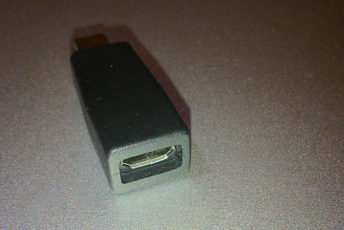
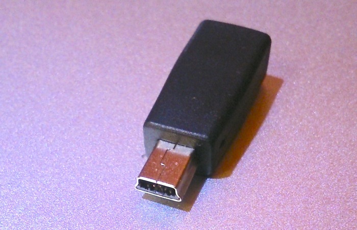
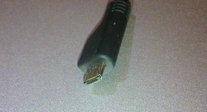
I was using an adapter from Micro-B to Mini-B, and sometimes it generates issues. This was because I was reusing a phone Usb wire:

DSC_0181

Now, I can set the FTDI jumper to the 3.3V and connect to the ESP8266 without any external power supply:

DSC_0185

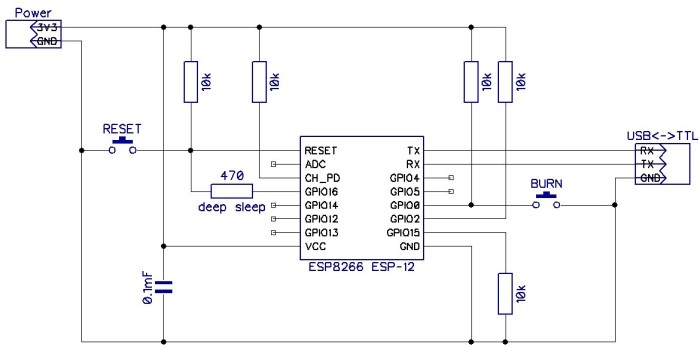
The final Schema that I am using is this:

Programming-Schema

If you do not have the push buttons, just leave the connections open and close the connection manually. You’ll know when to close the connection after reading the following paragraphs.

Update:

The ESP8266 works with this configuration, but it throws an exception when the WiFi connection is stablished. It looks like some connection needs to be improved (maybe WiFi needs extra power and makes the pic stop working). If you are about to program your ESP8266, please continue with the schema with External Power supply, till I find a solution.

The Esp8266, has different start modes. You can check which mode is started by connecting through Serial monitor (from Arduino Ide, or any other software), at 74880 baud rate:

 ets Jan 8 2013,rst cause:2, boot mode:(1,6)


 ets Jan 8 2013,rst cause:2, boot mode:(3,6)

load 0x40100000, len 612, room 16 
tail 4
chksum 0x12
load 0x3ffe8000, len 788, room 4 
tail 0
chksum 0x50
load 0x3ffe8314, len 264, room 8 
tail 0
chksum 0x4a
csum 0x4a

This is the output that I get in my computer. In the first start, the mode (1,6) is programming. It will be ready to receive a new binary file to be written in the memory. In the second start, the mode is normal. You can see that there is more information, like the reason of the restart (in this case, reset button was pressed by me).

You can restart your device by grounding the RST pin. You can do it by closing the RESET connection, or for making your life easier, you can use the push button. You can also remove the power pin and connect it again.

If you would like to upload a new program to your device, you need to start it in programming mode. In order to do this, you must ground the GPIO0 before starting your device, or just restarting it. You can do this by closing the Burn connection and then restarting your device.

When you buy the ESP8266 the device includes a default firmware. This firmware allows communication via something called “AT commands”. Via serial communication, you can send pre-defined commands that will allow you set up a WiFi connection, receive and send data. This is the slave-mode for use this device, that I will not cover.

Once you upload your own code, the AT commands are not available anymore, but you can recover it if you need, by just uploading the default firmware that you can download from the Espressif website:

http://espressif.com/new-sdk-release/

In this link you will find the Software Development Kit, and I think the firmware is included there.

In next posts I will talk about how to upload your code to the device with your computer.

Thinking further

Hi again folks,

in the previous posts I’ve talked about the esp8266 as the definitive solution for the project. However, thinking a bit more later, I have noticed that since this will work with WiFi, I can send the data through every device WiFi capable: computers, mobiles, tables, etc.

First idea, to save costs was to use the computer to save money in components and create a desktop application. However, that would be very difficult to control,as you will need to use the mouse and keyboard. Very complicated if you need to set several inputs at the same time.

Next idea, a tablet, with sliders that allows you to set trains speed and direction. Multitouch will allow you to set more than one item at one time. Looks reasonable.

Last idea:

I remembered about a very old equaliser abandoned at the top of a closet. I will never use it and it is there just gathering dust. I am thinking in using the sliders to control the trains and read the data with a raspberry Pie. The costs will be minimum. I prefer this idea than the tablet, as hardware devices are better for controlling.

Project Starts

The project is now starting and a lot of investigation is on the air now. First thing was to get two devices and do some POC. I went to aliexpress and bought two of this:


Next thing was to find out how to program it, and there are several ways to do it:

  • Espressif (the manufacturer) provides an API for programming the device and control wifi. Very extensive and complete.
  • Arduino Library has been adapted and can be used for coding this pic with the Arduino “IDE”.
  • Something called LUA, which is some kind of set of tools that will allow you to use C and the serial port for programming and debugging. I’ve read that it requires a big % of the micro memory, so I discarded it.

There are maybe more, I’ve read somewhere that you can use javascript also to code it.

I decided to go with Arduino, as I already have some knowledge, I can work on it with the Mac, and there is a lot of people developing on it.

First thing I noticed when testing the ESP8266, is that the model I got, has only two pins for input/outputs:

esp8266_pinout-2

I browsed the internet and found that there is a REV-12 model that has more pins:

91551-adafruit-esp8266-smt-module-esp-12-03-700x700
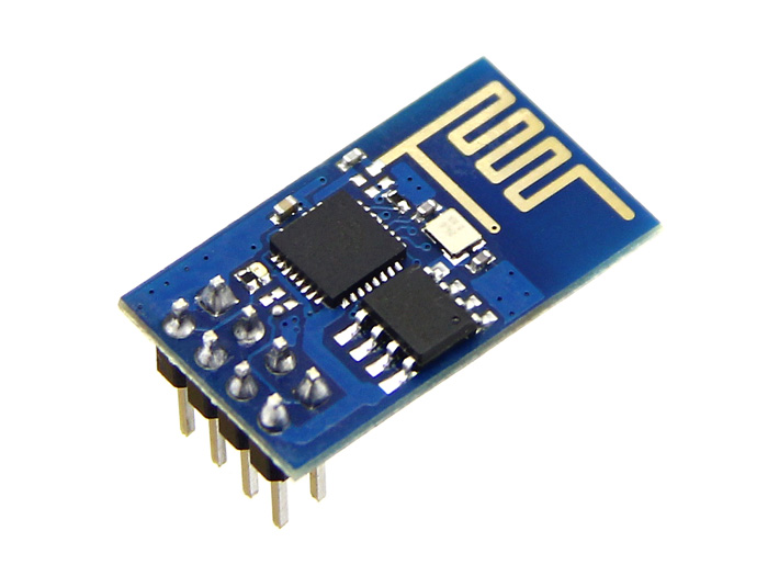
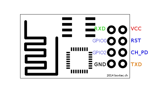
In this model, you have an ADC (anagogic to digital converter) input, and several GPIO (General Purpose Input Output) pins. I have also bought two of them for the first prototypes.

Let’s see how this goes. Keep tuned.

Wifi DCC H0 Project

Hi,

I am creating this post to introduce the new project that I am joining. Let me put you in context first:
maybe you know already about Train modelling. Is a hobby for people who like trains and small things, modelling, dioramas, and other similar staff. You have a railroad layout and a set of trains, and you drive them over the layout and enjoy the view. Some people creates a mini-world around it looking for the most realistic scenarios.

My dad owns a ver old set of H0 train set that works on an anagogic system. He created a layout for having them at home and drive them from time to time. The layout consists in two elipses sharing the center, one inside the other. There are two connections between them allowing trains to go from one to the other and get back. The full set runs on a 18DCV circuit ruled by two power supplies with a potentiometer to allow you regulate speed and direction. Every train consist in a Locomotive with a DC motor attached to the wheels for transferring the movement, and then behind all the wagons. Here’s a picture:

ho_0-6-0_sidetnk

And here is an random layout taken from the internet:260943

So, the railways act as conductors for the power and the wheels send the voltage to the Locomotive’s DC motors (some brands have a AC motor, but the railway is different and there are 3 lines for power conducting, something completely different). The amount of voltage sent to the Locomotive is decided in the controller.

At this point you probably noticed that this way, you can only drive one train at a time, or more than one, doing exactly the same as the others, as the signal will be the same for all of them. This project raises as the need of a solution for this situation, and the latest electronic components that I have found over the internet, and my knowledge with Arduino.

The aim for the project is to create a device as small as possible to be fit inside the locomotive (H0 is 1:87) and control it through digital signals. There are devices that will allow you to do it, and this is called DCC (digital command control) but the prices are very high, if you have a big set of trains that you would like to convert.

In the DCC approach, a constant power signal is sent through the railway and an encoded signal is mounted over it. This goes over the railroad constantly and every locomotive receives from the railroad the power to run, and the signal to be decoded. Once the locomotive read the signal, it checks if the signal is for this locomotive, and if this is the case, runs the command. This happens a lot of times per second, creating a sensation of continuos control.

My first idea was to create something similar, and send the signal over the railway. I have browsed the internet and found some related projects. Most of them refer only to the control side of the device. Actually all of them (the ones that I’ve seen and found) and they all use DCC ready locomotives. Is a valid approach but not suitable for my case.

I thought about creating a decoder for the trains, but I have no information on how to do it, so if you, reader maybe know about something, please contact me. Instead, I’ve found this:

ESP8266 | Espressif 乐鑫

This is a micro controller with WiFi attached to it. My first idea was to control it with an arduino (ATMega) but it turned out that there is a full pic on it, and you can code it. There is no need to have the arduino. This is the perfect device for controlling mobile devices over IP.

The idea now is to send a constant power signal over the railway, and send the data over WiFi. For that, I just need to have a power supply to the device (it runs at 3.3V and trains around 18V), and control the motors with a DC motor driver. It looks promising.

Welcome to the project!

What is DieCast Cars?

DieCast Cars is an Android Application created to manage small cars collections. It is expected to be available also on iOS and Windows Phone in the future.

Logo used in the Google Play Store

The main purpose is to have a local database on your phone where you can browse your collection whenever you are. It allows you to add all the information you want, including pictures. Features have been developed to add all your cars information and pictures to your device in a super fast and easy way.

If you already have a database of your cars in XLS (Excel), CSV, or TXT files, you just need to send it to your phone and DieCast Cars will allow you to instantly add your cars to your Mobile database. If you want to add also pictures, you do not need to deal with changes between interfaces thanks to the UltraCamera feature. It will allow you to just take all the pictures together in one single step and the pictures will be automatically.

Look for more information in this site if you want to know more!

We have gone live in Android!

We are very happy to announce that we have already gone live to Android! It took us some time to get this application ready but we finally did it.

Last week we released our last version 1.0 to our crowd. The application has been developed for the Android Platform, it includes several features that will help you manage your collections and keep your data close to you all the time, translation in 3 different languages (English, Spanish and Polish) and it is compatible with Android devices since Android 2.1.

You can find it in the Google Play Store following this link: Diecast Cars

Feel free to give it a try and check what is going on inside! Thank you for rating it.

The blog is now online!

Hello World! This is my first public blog to the world. I have created it to have a way to keep in touch with the users of my applications. I am close to release my first Android App about managing collections. I am sure it will be some bugs or things to improve, so I think this blog will help me to receive the opinions and suggestions of users who are enjoying the applications. This is a place open to talk and to expose your ideas, if you are user of any of my applications, please share your opinion with us.